# LTE-M Dongle I am increasingly using my home automation system, and I wanted a backup connection in case my primary Internet connection fails. Since I plan to place it on a small UPS, this will also address power failure scenarios. The obvious option would be to use a 3G/4G/5G radio modem, but it seems like overkill for, hopefully rare, SSH access to a remote computer. In addition, such modems often have a weak internal antenna for indoor reception, and lack an easy way to add an external antenna. After exploring various alternatives, I identified an LTE-M modem as a suitable solution. It offers better sensitivity than a standard LTE modem, operates on low power (good for UPS usage), and while it doesn't offer high throughput, it is more than sufficient for my intended use. On the downside, many LTE-M modems only provide a serial port for sending vendor-specific AT commands to open UDP or TCP connections, and I wanted to avoid developing dedicated software to interface with my home automation system. Fortunately, looking at the various available LTE-M modules, I have discoverd the SIMCOM SIM7080G module, which is based on a Qualcomm modem, and feature a high-speed USB interface that can appear as a network interface on my Linux system. That led me to design my own LTE-M dongle with an SMA connector to accommodate an external antenna. ## Photos [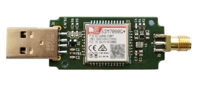](images/lte-m-dongle-top.jpeg) [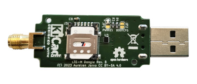](images/lte-m-dongle-bottom.jpeg) [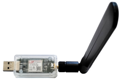](images/lte-m-dongle-enclosure.jpeg) ## Hardware The board was designed using [KiCad](https://www.kicad.org/) 6.0. The [schematic](images/schematic.png) is relatively simple, and centers around the [Simcom SIM7080G](https://www.simcom.com/product/SIM7080G.html) LTE-M and NB-IoT modem, which is small enough to fit in a [Hammond 1551USB2](https://www.hammfg.com/electronics/small-case/plastic/1551usb) enclosure, my standard choice for dongles related to home automation, while still hand solderable. The high-speed USB interface is connected to the USB connector through the corresponding ESD protection and power filtering, while the UART, I²C, SPI and PCM interfaces are left unconnected. The GNSS feature can not be used simultaneously with the LTE-M connection, so it is unused in this dongle, and the corresponding antenna is left unconnected. The module requires a 3.8 V power supply. It is generated from the 5 V USB through a [TPS62A01](https://www.ti.com/product/TPS62A01) buck converter for higher efficiency. A nano-SIM card connector is also connected to the module, along with two LEDs providing status feedback: LD1 for the network status and LD2 for the module status. Two solder jumpers are also present, one to switch the module to firmare update mode, and the other one for the power-up configuration. The latter jumper deserves some additional explanations. The module is off by default, and can be powered on by briefly pulling the PWRKEY pin to ground. However this pin can not be shorted all the time to GND as the module switches off when this pin is pulled down for approximately 12 seconds. To ensure the module remains permanently on, a trick is used: connecting that pin through a resistor to the 1.8 V power supply generated internally by the module. When the module is off, this voltage is close to 0 V, powering on the module. Once the module has started, the 1.8 V power is available, and thus the pin is no longer pulled low. This also means the module will automatically restart after being powered off. This feature is selectable by a jumper: either short pin 1 and 2 together to keep the module running permanently or connect an external system shorting the pins 2 and 3 to control the power of the module. The PCB is a four-layer design, required to provide 50-ohm impedance for the RF trace and the 90-ohm differential impedance for the high-speed USB traces. The bottom side accomodates the nano-SIM connector and the jumpers, making them accessible by removing two screws from the enclosure. The top side houses the SIM7080G module and everything else, including the two LEDs, visible through the transparent enclosure. All the components from the [bill of material](BOM.txt) should be easily available from many distributors. Soldering of the SIM7080G module requires a hot air gun, but the LGA style pads are relatively large, so it's relatively easy to do. I personally didn't use a stencil. ## Software ### Useful AT commands When connected on an USB port, the modem provides four CDC ACM serial interfaces, appearing as `/dev/ttyUSBx` on Linux. The AT commands can be sent on the third and four interfacs. Here are a few useful AT commands to check that the LTE-M modem work correctly: - Display the manufacturer of the module ``` AT+CGMI SIMCOM_Ltd OK ``` - Display the model of hte module ``` AT+CGMM SIMCOM_SIM7080 OK ``` - Display the firmware revision of the module ``` AT+GMR Revision:1951B07SIM7080 OK ``` - Display the product identification information of the module ``` ATI R1951.04 OK ``` - Display the International Mobile Equipment Identity (IMEI) of the module ``` AT+GSN 8600xxxxxxxxxxx OK ``` - Check if PIN code is required ``` AT+CPIN? +CPIN: SIM PIN OK ``` - Entering PIN code if required ``` AT+CPIN=1234 OK ``` - List available operators ``` AT+COPS=? +COPS: (1,"F-Bouygues Telecom","BYTEL","20820",9),(1,"F-Bouygues Telecom","BYTEL","20820",7),(1,"F SFR","SFR","20810",9),,(0,1,2,3,4),(0,1,2) OK ``` ### Internet connection The modem should be recognized directly by the Linux system, it provides a CDC Ethernet interface. Configuring it with DHCP already provides an Internet access. However I prefered to use a PPP connection over the CDC ACM interface as it allows for monitoring the availability of the Internet connection. To do this on a Debian Bookworm installation, I installed the [`ppp`](https://packages.debian.org/bookworm/ppp) package. The default `gprs` script works fine after replacing `/dev/modem` by the serial device corresponding to the USB modem. The modem provides multiple CDC ACM interface, in my case I used the fourth interface through the `/dev/serial/by-id/usb-SimTech__Incorporated_SimTech_SIM7080_1234567890ABCDEF-if03-port0` device. Addressing the device by ID is also useful, as I have other USB devices with serial interface on the host, and their order is not stable. However, it seems that the serial number is not properly filled by the manufacturer, so it's probably not possible to use the two of these modems of the same host. To start the start the Internet connection automatically when the modem is plugged into the USB port, and to restart it automatically in case of connection failure, I used the following systemd unit: ``` [Unit] Description=PPP Daemon ConditionPathExists=/dev/serial/by-id/usb-SimTech__Incorporated_SimTech_SIM7080_1234567890ABCDEF-if03-port0 After=network.target [Service] ExecStartPre=/bin/sleep 1 ExecStart=/usr/sbin/pppd nodetach linkname ppp0 call provider KillMode=mixed Restart=on-failure RestartSec=30 RestartPreventExitStatus=SIGKILL [Install] WantedBy=multi-user.target ``` Once the connection is started, LD1 should blink with a 300 ms period. ### Backup connection strategy My LTE Internet provider only provides a private NATed IPv4, so I use a [Wireguard](https://www.wireguard.com/)-based VPN to be able to access the my home automation system remotely. Since I do not want the LTE connection to be the default one, I added a `nodefaultroute` option to `/etc/ppp/peers/provider`, and I instead added a manual route to my Wireguard server. Therefore as long as at least one of the two Internet connections (fiber and LTE) is available, my home automation system is accessible remotely. For the outgoing traffic, I also added a manual route to my mail and SMS servers to ensure they are routed through the Wireguard VPN, so alert messages can always be sent. ## License The contents of this repository is released under the [Creative Commons Attribution-ShareAlike 4.0 International License (CC BY-SA 4.0)](LICENSE).